Before I started to build my Headhunter model, I needed to create two planes for my blueprint images. I used the create tool to create a plane, and adjusted the size so that it was the same size as the image. I then went to the Material Editor to import the image file using a bitmap and then added the image layer to the plane. I did this for both the planes.
I used the Rotate tool to position the images correctly. I also used the Align tool to make sure the two images were positioned evenly together so it would make it easier and more accurate when it came to making my model.

Now that I had my two images in position, I wanted to start making my model. To begin with, I created a box and adjusted the parameters so that they matched the dimensions of the ships body on the images.

I typed in the lengths to make it more accurate, but did not make it the exact size as I was going to adjust this later on using the Vertex's of the box. I also added more segments (four) for the Length, Width and Height of the box so it would make it easier when it came to altering the shape later on.

Once I had the basic box shape for the body, I right clicked on the shape and chose the 'Convert To' then 'Editable Poly', and selected 'Vertex' from the new drop down menu. All the vertex's of the box now appeared and using the 'Select and Move' tool I pulled out the front vertex's so they were the full length of the body. I then used the 'Scale' tool and clicked and dragged in the small yellow box to narrow the front to match the image.
I did the same with the back vertex's only I didn't narrow them to the same degree as the back of teh ship was not as pointed.
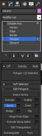
On the 'Editable Poly' drop down menu, I now chose the 'Polygon' option. I then selected the top polygons, holding down the 'ctrl' shortcut key on the keyboard so I could select multiple polygons at the same time. I then used the 'Select and Move' tool to push the polygons up so they were the correct height of the body as shown in the images. I also used the 'Scale' tool to push the polygons inwards so that they became narrower. I used the Polygon option for this as I didn't want the edges to be as smooth for the top as they were a bit more edgy in the image.
I again selected the 'Vertex' option from the 'Editable Poly' menu, and selected columns of vertex's and moved them along to correspond to the image. Then, using the 'Scale' tool and dragging in the small yellow box, I narrowed out the box so that it became smoother and matched the body shape shown on the image. I used the vertex option for this because I wanted the rest of the body to be smoother and more curved.

Now that I had the main part of the body made, I wanted to make the pointed nose on the front of the ship. I did this by once again creating a box. This time to a much smaller scale. I changed the dimensions of the box in the 'Parameters' panel and once again added more segments for each so it would be easier to edit.

As you can see, I didn't make the box the full length of the nose to start off with as I intended to alter and drag out the vertex's to create more of a defined point instead.

Like previously, I right clicked on the shape and converted it to an 'Editable Poly', and clicked on the 'Vertex' option in the menu.

Once the vertex's appeared, I selected the very front ones and using the 'Select and Move' tool, I pushed them forward to the point of the nose of the image. I then selected the very top vertex's and dragged them down towards the centre of the box. I did the same for the very bottom vertex's as well, in order to create a sharp point to match the image.
After this I selected some columns of vertex's and dragged them along using the Move tool. I then selected the top and bottom vertex's individually and dragged them inwards slightly to create a smoother narrower edge.
I also altered the width of the box by selecting certain vertex's and pushing them inwards so the nose was more accurately positioned.

Now that I'd finished creating the nose, I wanted to make the wind sheild. To do this, I created a small cylinder the same size as the widest point and not to the exact length. I made it so part of the bottom of the cylinder was in the body of the ship as I only wanted part of the cylinder on show.
Additionally in the Parameters panel I added more segments so it would be easier to edit the cylinder later and to make it more curved.

Once I'd got the basic cylinder shape, I converted it into an 'Editable Poly' and chose the 'Vertex' option again. I selected the front vertex's of the cylinder and used the 'Scale' tool to make it really narrow and pointed. I then used the 'Move' tool to drag the vertex's to the full length of the sheild and then dragged them down into the main body of the ship to make a smooth curved edge.
I moved some of the other vertex's along the cylinder too, to change the size and position of them so the edges became more curved to match the shape of the sheild in the image.

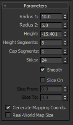
I now wanted to create the big engine body at the back of the ship so I created another cylinder; this time to a much larger scale. Again, I added more segments to make it easier to edit later on.

Once I'd created a basic cylinder, I converted it into an 'Editable Poly' and chose 'Vertex' on the menu. I selected all the vertex's nearest to the front and using the 'Move' tool, I pushed the vertex's up slightly so that they matched the same positioning on the image.
On the second column of vertex's I used the 'Scale' tool to make the radius slightly wider, I dragged in the yellow box so that all axis's were changed to the same degree. I then used the 'Move' tool to drag the vertex's up and along to create a similar curve to the image.
I moved the rest of the vertex's along slightly and moved them up and down to correspond to the image too. On the last set of vertex's I used the 'Scale' tool to make the end just a bit narrower to the rest.

After I had positioned and changed the shape of my cylinder. I now wanted to create the wings of the ship. I started out by creating a really long thin box, which spanned across the ship.

I changed the 'Parameters' accordingly, making sure the dimensions were correct and added more segments too.

Once I had the basic shape for my wing, I needed to change the shape so that the box looked more like a wing. I did this by converting the box into an 'Editable Poly' and selecting 'Vertex' in the panel.

I started shaping my wing by firstly selecting the vertex's closest to the back end and nearest to the body of the ship. Using the 'Select and Move' tool I moved some of the vertex's inwards to start creating a thinner edge. I made sure that when moving my vertex's inwards, none of them crossed over as this would've caused a fault in my ship when rendered.

I used the same process to move the rest of the vertex's nearest to the edge inwards too, so that the wing got wider the closer it moved into the ship, which made it look more realistic.

After I'd shaped my wings, I now wanted to change the width of them so that they got thicker the closer they got to the body.

I started on the right wing of the ship, and on the vertex level, I selected the top vertex and using the 'Move' tool I pulled the vertex up to the same height as on the image. I used the same method to move the bottom vertex down too. This made the wing much thicker near the body.
For some of the other vertex columns, I moved them along slightly depending on where I wanted to change the thickness of the wing slightly, and used the same technique as before to adjust the thickness.
For the vertex's nearest to the outside, I made them much thinner than the rest, so in this case instead of pushing the vertex's out, I moved them in to get a more pointed edge.
Although I started out with one complete wing, I actually decided to change this as I was making the model. In the end I deleted on the vertex's on the left hand side, so I was just left with the right wing. I did this because I wanted to mirror the right wing to make the left, which means they would both be completely identical.
To mirror the wing I simply went to the 'Mirror' icon on the top menu, which bought up the 'Mirror' window. I made sure the 'Copy' option was selected so that it made an identical clone when mirrored. I then selected the correct axis that I wanted the mirrored image on and clicked 'OK'. Once my mirrored wing was made, I then used the 'Move' tool to move the wing directly across to the otherside and into place. I now had two completely identical wings.

The next thing to add was the small guns on the end of each wing. To make these, I created a short cyclinder, roughly the same legnth as the wing. I changed the dimensions and added more segments as well. I also converted my cylinder into an 'Editable Poly' and chose the 'Vertex' option from the menu.

For the vertex's at the very end, nearest to the front, I pulled them out using the 'Move' tool so they were the correct length. I then used the 'Scale' tool and clicked and dragged in the small yellow box to make the end more thin and pointy. I then dragged another two columns of vertex's along to different points, which I both made thinner by using the 'Scale' tool. For the other vertex's I made slightly thicked and curved.
Once I'd made the wing gun on one side, I cloned the object using the shortcut 'ctrl' + 'v' , this brought up the 'Clone' window where I changed the name accordingly and pressed 'OK'. Now that my gun was cloned I simply used the 'Move' tool to move it directly across to the other side and placed it in position.

I now wanted to start making the four engines on the ship. I began this by creating a cylinder and adjusted the dimensions and added segments in the 'Parameters' panel like I'd done before.

Once the cylinder was in place I converted it into an 'Editable Poly' and chose the 'Vertex' option.


To move the cone into the exact place I wanted, I used the 'Move' tool so that it was positioned directly in the centre of the front of the engine.


I then moved my cone into the centre of the back of the engine using the 'Move' tool, making sure it was evenly positioned.

Once my cone was in place and selected, I went to the 'Compound Objects' menu and chose the 'Boolean' option. I then clicked on the 'Pick Operand B' option and selected the engine. I made sure that under the 'Operations' panel, the option 'Subtraction (B-A)' was selected.

 To mirror the engine I selected all the different components of the engine, using the 'ctrl' key, and then selected the 'Mirror' tool on the top menu. When the new Mirror window appeared on the screen, I made sure the 'Copy' option was on so I got a new clone of the object. I then selected the right axis that I wanted to mirror it to, and clicked 'OK'.

Now I had finished building all my engines, my model was complete.

After the vertex's all appeared on the screen, I pulled out the end vertex's on the last edge using the 'Move' tool. I then made the end narrower by using the 'Scale tool. I also pulled the next two columns of vertex's along as well and scaled them to make them slightly narrower.
I added a bit of detail along the cylinder by scaling more vertex's so they were more curved like in the image. On the last vertex's, the ones closest to the front, I also scaled so they were slightly narrower too.

Now that I had the shape of the engine I wanted to add some detail to the front and back of it. To start with I wanted to create a small hole in the front. To do this, I created a small cone, without added the point at the top. I adjusted each radius of the cone so that it was just right to fit into the engine.
To move the cone into the exact place I wanted, I used the 'Move' tool so that it was positioned directly in the centre of the front of the engine.
I now wanted to use the 'Boolean' tool so that I could cut out the cone shape from the engine cylinder. I did this by going to the 'Compound Objects' menu on the right and then selecting the 'Boolean' option.
I already had the cone selected for Operand A, so I clicked the 'Pick Operand B' button on the right panel and then clicked on the engine cylinder. I also had to make sure the opteration 'Subtraction (B-A)' was selected.

My hole had now been created in my cylinder.

I now wanted to add some more detail to the front of the engine as on the image two cylinders were shown just inside. To do this, I created a cylinder and made it just the right length to fit in the front of the engine. I then used the 'Scale' tool to and squashed the cylinder slightly so it was no longer perfectly rounded.
Once I had done this, I cloned the image using the shortcut 'ctrl' + 'v'. I then rotated the cylinder round 90 degrees so it was positioned vertically rather than horizontally. I needed to change the length of the cylinder as I only wanted it to be half the size. I used the 'Scale' tool again to do this and pushed down on the end of the cylinder so it became shorter.
Now that the front of my engine was complete, I needed to add a small hole to the back of the engine, similar to how I did the front. I started by creating a small cone again, without the point to it. I changed the size in the 'Parameters' panel again to be more accurate.
I then moved my cone into the centre of the back of the engine using the 'Move' tool, making sure it was evenly positioned.
Once my cone was in place and selected, I went to the 'Compound Objects' menu and chose the 'Boolean' option. I then clicked on the 'Pick Operand B' option and selected the engine. I made sure that under the 'Operations' panel, the option 'Subtraction (B-A)' was selected.
Now that the detail on my engine was complete. I wanted to mirror it, to create the bottom engine, jsut underneath.
To mirror the engine I selected all the different components of the engine, using the 'ctrl' key, and then selected the 'Mirror' tool on the top menu. When the new Mirror window appeared on the screen, I made sure the 'Copy' option was on so I got a new clone of the object. I then selected the right axis that I wanted to mirror it to, and clicked 'OK'. Once the engine was mirrored, I simply moved it into position just underneath the top engine by using the 'Move' tool.
Now that I had both of the right engines into position, I wanted to clone them both to make the left engines. I did this by selecting all the components of both engines holding down the 'ctrl' in the process, and then pressed the cloning shortcut 'ctrl' + 'v', which bought up the Clone menu where I pressed 'OK'.
Once the engines were cloned, I moved them directly across using the 'Move' tool into the correct position.

Now I had finished building all my engines, my model was complete.


